Introduction When selecting a power inductor for a switching converter or any power electronics application, one of the most critical — and most frequently misunderstood — specifications is the current rating. A datasheet typically lists three different current values: saturation current (Isat), temperature rise current (Irms), and rated current (Irat). Each describes a fundamentally different limitation, and confusing them can lead to premature component failure, unreliable converter operation, or costly over-design. This article breaks down each current rating, explains the physical mechanisms behind them, and provides practical guidance for making robust design decisions. 1. Saturation Current (Isat) Definition The saturation current is conventionally defined as the DC current at which the inductance drops by approximately 30% from its initial, zero-current value. Physical Mechanism Most power inductors incorporate a magnetic core — typically ferrite, powdered iron, or a similar high-permeability material. The core serves to concentrate magnetic flux and boost inductance for a given number of turns and physical volume. However, all magnetic materials have a finite flux-carrying capacity. As the current through the winding increases, the magnetic flux density inside the core rises. Once the core approaches its saturation flux density (Bsat), the permeability collapses sharply, and the inductance plummets. This is not a gradual, linear process. The inductance-versus-DC-bias curve is relatively flat at low currents and then rolls off steeply as saturation sets in. A 30% inductance drop is the industry-standard threshold used to characterize this onset of saturation. ⚡ Key Characteristic: Instantaneous Saturation current is an instantaneous rating. It does not matter whether the high current lasts for microseconds or minutes — if the peak current reaches Isat, the core can enter saturation. This distinction is critical in switching regulators, where the inductor current consists of a DC component plus a triangular ripple. The peak current (DC plus half the peak-to-peak ripple) is what must be compared against Isat, not the average or RMS value. Consequences of Exceeding Isat If the peak current exceeds the saturation current, the inductance drops abruptly. In a buck converter, for example, this means the inductor can no longer limit the slope of the current rise during the switch on-time. The switch current stress spikes upward, potentially exceeding the MOSFET's safe operating area and leading to catastrophic device failure. In severe cases, the inductor effectively becomes a short piece of wire, and the converter loses regulation entirely. Datasheet Example Consider a 1.0 µH power inductor specified at a 1 MHz test frequency. Its datasheet lists: Parameter Typical Maximum Saturation Current (ΔL = 30%) 4,900 mA 4,300 mA DC Resistance 44 mΩ 53 mΩ The accompanying DC bias curve shows inductance holding relatively steady at low currents, then gradually declining and dropping more steeply as the bias current approaches the saturation threshold. ️ 2. Temperature Rise Current (Irms) Definition The temperature rise current — often labeled Irms or I_rise on datasheets — is defined as the DC current at which the inductor's self-generated temperature rise (ΔT) reaches approximately 40°C above ambient. Physical Mechanism Unlike saturation current, which is governed by magnetic physics, temperature rise current is a thermal limitation. Current flowing through the inductor's copper winding encounters DC resistance (DCR), dissipating power according to Joule's law: P = I² × DCR This power is converted into heat, which raises the inductor's body temperature above the surrounding ambient. The temperature rise is not linear with current — because power scales with the square of current, the temperature-versus-current curve is approximately exponential. Once ΔT reaches 40°C, even a small additional current increment causes a disproportionately large temperature jump. Key Characteristic: RMS / Continuous Temperature rise current is a continuous, RMS-equivalent rating. It describes how much current the inductor can carry on a sustained basis without overheating. In a switching converter, the appropriate comparison is the RMS current through the inductor, which accounts for both the DC level and the AC ripple component. ️ Relationship to Operating Temperature Range Datasheets specify an operating temperature range, typically −40°C to +125°C, with the note "(including self-heating)." This means the 125°C upper limit is the sum of ambient temperature plus the inductor's self-generated temperature rise. This relationship has a direct practical implication. If the maximum ambient temperature in the application is 85°C, then the inductor can tolerate a self-heating of up to 40°C (85°C + 40°C = 125°C). Under this condition, keeping the RMS current at or below the temperature rise current ensures the inductor operates within its thermal limits. However, if the ambient temperature exceeds 85°C, the allowable self-heating budget shrinks, and the current must be derated accordingly. Datasheet Example A typical datasheet footnote states: Isat : DC current (A) that will cause L0 to drop approximately 30%. ️ Irms : DC current (A) that will cause a temperature rise ΔT of approximately 40°C. ✅ Rated current : The lower of the saturation current or the heating current. ️ Operating temperature : −40°C to +125°C (including self-heating). The temperature-rise characteristic curve plots ΔT against DC current for inductors of different values (e.g., 22 µH, 10 µH, and 2.2 µH in the same package). Higher-inductance parts — which require more turns and therefore have higher DCR — reach the 40°C threshold at lower currents. For example, a 22 µH part might hit 40°C at roughly 0.8 A, while a 2.2 µH part in the same footprint can carry over 2 A before reaching the same temperature rise. ✅ 3. Rated Current (Irat) Definition The rated current is simply the smaller of the saturation current and the temperature rise current. It represents the maximum current at which the inductor can operate under normal conditions without violating either its magnetic or thermal limits. Irat = min(Isat, Irms) ❓ Why Two Limits Are Necessary Saturation and temperature rise describe independent failure modes. Depending on the inductor's design — core material, core size, wire gauge, number of turns — either one can be the binding constraint: Low-DCR, high-saturation designs (e.g., large-gauge wire, low turns count) may be thermally limited first. The temperature rise current is lower than the saturation current. High-inductance, high-turn designs may saturate magnetically before reaching the thermal limit. The saturation current is the lower value. The rated current captures whichever limit is reached first, giving the designer a single, conservative number. Worked Example Using the 1.0 µH inductor from the earlier datasheet: Parameter Typical Maximum Saturation Current (ΔL = 30%) 4.9 A 4.3 A Temperature Rise Current (ΔT = 40°C) 3.6 A 3.3 A Rated Current — 3.3 A Here, the temperature rise current (3.3 A max) is lower than the saturation current (4.3 A max), so the rated current is 3.3 A. This inductor is thermally limited — it will overheat before it saturates. For reference, the full datasheet entry for this part also includes: Parameter Value Inductance 1.0 µH ± 20% Case Size (EIA/JIS) 1008 / 2520 DC Resistance (max / typ) 53 mΩ / 44 mΩ LQ Measuring Frequency 1 MHz Operating Temp. Range −40 to +125°C (including self-generated heat) ️ 4. Design Guidelines and Margin ✔️ Two Independent Conditions A robust design must satisfy both of the following conditions simultaneously: Peak instantaneous current ≤ Saturation Current 1. — ensures the core never enters saturation, even during transient load steps or startup. RMS current ≤ Temperature Rise Current 2. — ensures the inductor operates within its thermal budget under steady-state conditions. Meeting only one of these is insufficient. An inductor that never saturates can still overheat and degrade over time; conversely, an inductor that runs cool can still suffer catastrophic saturation during a load transient. Recommended Margin As a general rule, design with a 20% to 30% margin below both current limits. This headroom accounts for: Component tolerances (inductance ±20%, DCR variations) Production lot-to-lot variation in core characteristics ️ Ambient temperature extremes beyond nominal ⚡ Transient currents not captured in steady-state analysis ⏳ Aging effects on core permeability and winding insulation Practical Selection Workflow 1. Calculate the required inductance based on switching frequency, input/output voltage, and allowable ripple current. 2. Determine the worst-case peak current (maximum load current + half ripple + transient overshoot). 3. Calculate the RMS inductor current under full-load conditions. 4. Select an inductor whose maximum-rated saturation current exceeds the peak current with margin. 5. Verify that the maximum-rated temperature rise current exceeds the RMS current with margin. 6. Confirm thermal performance at the actual maximum ambient temperature, derating if necessary. ⚖️ 5. Typical vs. Maximum: Why the Numbers Differ A common point of confusion is why datasheets list both "typical" and "maximum" values for current ratings — and why the maximum is sometimes lower than the typical. Typical Value The typical value represents the average performance of parts coming off the production line. It reflects what a well-centered, nominal unit will do. It is useful for estimating typical circuit performance and for comparing products across vendors, but it is not a guaranteed limit. Maximum Value The maximum value is a guaranteed specification from the user's perspective. The manufacturer commits that every single unit shipped will meet or exceed this value. To make this guarantee across the full production distribution — including worst-case material batches, process variations, and temperature extremes — the maximum rating must be set below the typical value. In other words, the gap between typical and maximum is the manufacturer's margin for process variation. A part at the tail of the distribution may only achieve the maximum rating, while the average part achieves the typical. Design Implication Always use the maximum (worst-case) values as your design constraints, not the typical values. Designing to typical specifications means that a statistically significant fraction of production units will fail to meet your requirements. The typical values are useful for performance estimation and efficiency calculations, but the hard limits for reliability are the maximum ratings. Conclusion Inductor current ratings are not a single number — they are a set of interrelated specifications that describe different physical limitations: Saturation Current (Isat) defines the magnetic limit, triggered when the core's flux density reaches saturation and inductance collapses. It is an instantaneous, peak-current constraint. ️ Temperature Rise Current (Irms) defines the thermal limit, determined by I²R heating in the winding. It is a continuous, RMS-current constraint. ✅ Rated Current (Irat) is the lower of the two, representing the maximum safe operating current under normal conditions. By understanding which limit is binding for a given application, designing with adequate margin, and always relying on worst-case maximum specifications, engineers can select inductors that deliver reliable performance over the full product lifetime.
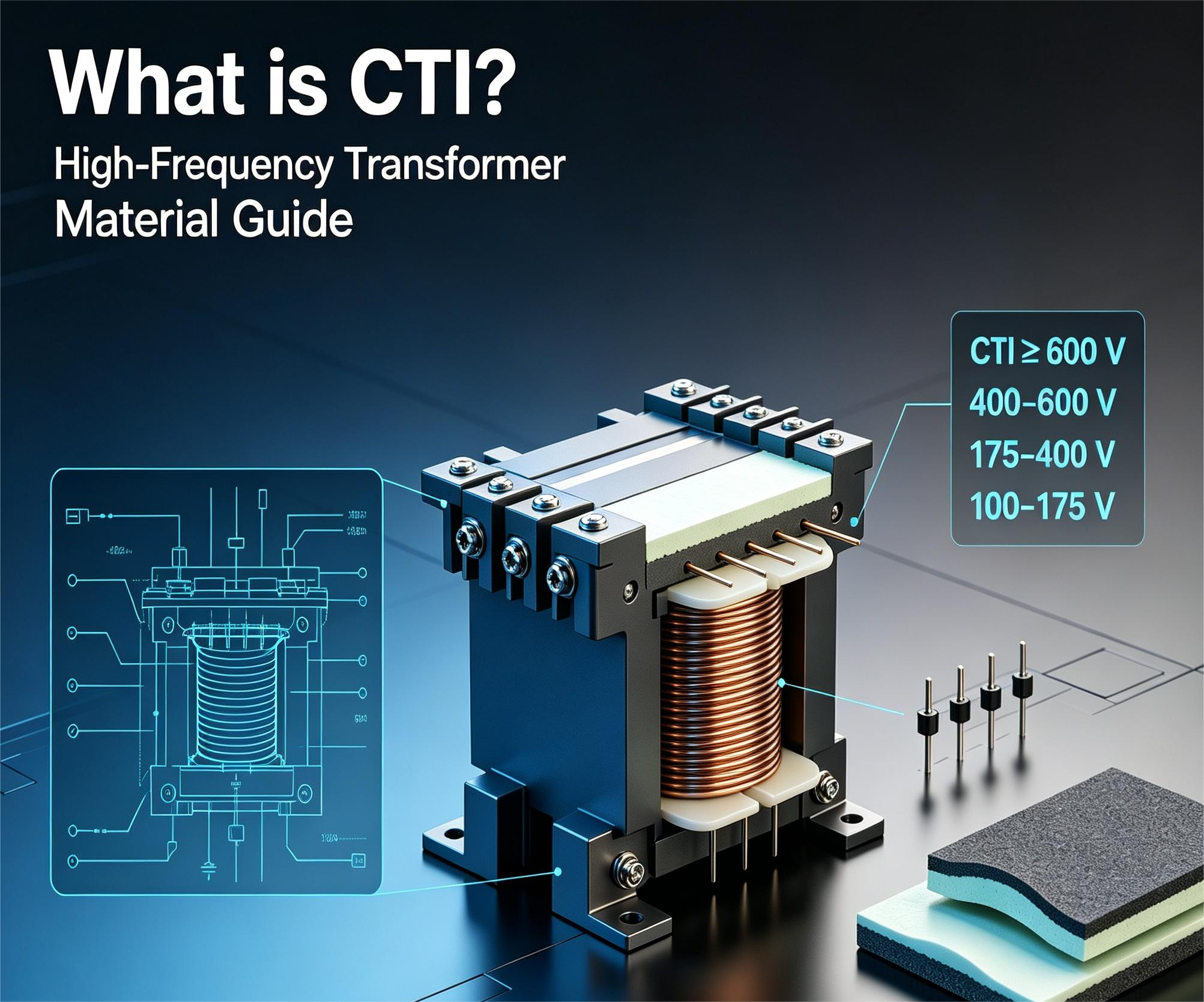
In high-frequency transformer design and material selection, the CTI of a material is of particular importance. It affects not only the creepage distance of the transformer, but also its safety and service life. The "CTI" of high-frequency transformer materials is the abbreviation of Comparative Tracking Index — the relative tracking index of an insulating material. It is defined as the highest voltage at which an insulating material can withstand 50 drops of a 0.1% ammonium chloride electrolyte solution without forming a tracking path on its surface. CTI is a key electrical property of materials; it determines the maximum voltage leakage path that a material surface can withstand. The higher the CTI, the shorter the required creepage distance, the stronger the material's resistance to electrical tracking and leakage current, and the more suitable it is for high-voltage and high-frequency applications. Commonly used insulating materials are classified into four groups by CTI value (per IEC 60112 / IEC 60664-1): The commonly used bakelite (phenolic molding compound) materials PM-9630 and PM-9820 belong to Group IIIa (PM-9630: measured CTI = 175 V per IEC 60112; PM-9820: CTI within 175–250 V per its UL Yellow Card), while the plastic materials WH9100 and WH8100 belong to Group I, meeting the CTI ≥ 600 V requirement.
 +86 0519-83330902
 sales@feiyangelec.com